vendredi 26 septembre 2014

Mini Programmateur de PIC sur le port USB

Mini Programmateur de PIC sur le port USB
Ce montage présente un mini programmateur de micro-contrôleurs PIC sur le port USB, avec une taille de 8*4cm et ne nécessitant pas un cordon USB.


Les programmateurs de PIC sont très répandus sur internet.
Réaliser un programmateurs de PIC en vous inspirant de ce montage: Programmateur de PIC sur le port USB auto alimenté. La raison pour laquelle j'ai voulu un micro programmateur USB est tout simplement pour sa portabilité, car la taille du programmateur déjà publié et le cordon USB ont été un inconvénient majeur et je trouvais ça trop contraignant.


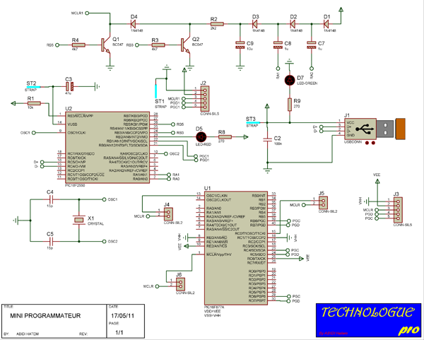
 Schéma du programmateur :


Le circuit est composé de plusieurs parties:


  • L'alimentation qui est fournit par le port USB,
  • Un circuit à pompe de charge qui fournit la tension de programmation à partir de l'alimentation USB,
  • Un support ICSP (In Circuit Sérial Programmeur),
  • Le cœur du montage : le PIC18F2550,
  • Des jumper pour sélectionner le type de composant à programmer (8/18/28/40 broches),
  • Un support ZIF ou deux supports 40 broches

Liste des composants :
Liste des composants du MINI PROGRAMMATEUR USB


6 Résistances

Quantité:
Références
Valeur
Rq

1
R1
10k
1/4 W

1
R2
2k2
1/4 W

2
R3, R4
4k7
1/4 W

2
R8, R9
270
1/4 W
7 Capacités

Quantité:
Références
Valeur
Rq

1
C2
100n
Céramique

1
C3
47u
Chimique

2
C4, C5
15p
Céramique

2
C7, C8
1u
Chimique

1
C9
10u
Chimique
2 Circuits integrés

Quantité:
Références
Valeur
Rq

1
U2
PIC18F2550


2 Transistors

Quantité:
Références
Valeur
Rq

2
Q1, Q2
BC547


6 Diodes

Quantité:
Références
Valeur
Rq

4
D1-D4
1N4148


1
D5
LED
Rouge

1
D7
LED
Verte
10 Autres

Quantité:
Références
Valeur
Rqe

1
J1
USB CONN
USB Type A

2
J2, J3
CONN-SIL5


3
J4-J6
CONN-SIL2


1
U1
Support ZIF
40 Broches

3
ST1-ST3
STRAP


1
X1
CRYSTAL 12MHz


Version imprimable de la liste des composants du programmateur
Réalisation:


Afin de réduire la taille au maximum, ce programmateur est composé de deux parties qui vont ensuite être montées ensemble

Vue 3d de la carte electronique

Le tracé du circuit imprimé et l'implantation des composants est proposé ci dessous:
Circuit imprimé


Fixation du programmateur

Ce programmateur permet la programmation In-situ des microcontrôleurs PIC, grâce à son interface ISP. Cette interface autorise la programmation directe des composants soudés sur les circuits imprimés ou des composants en boîtiers spéciaux.


Programmation In-situ des microcontrôleurs


Configuration du programmateur:
L'implantation des différents microcontrôleurs sur le support ZIF est faite selon le schéma suivant :


positionnement des microcontrôleurs

Le logiciel pilotant le programmateur de PIC : 
C'est le logiciel WinPic800 V3.55G qui prend en charge ce programmateur USB.


le programme du PIC18F2550 ce trouve dans WinPic800-3.55G/PIC18F2550 HEX.

Le logiciel WinPIC 800 V3.55G permet une gestion efficace et rapide du programmateur USB : 

  • WinPic 800 V3.55G détecte automatiquement le PIC placé sur les supports du programmateur,
  •  WinPic 800 V3.55G ne nécessite aucun réglage.
Procédure d'installation du programmateur 
Une fois que vous avez réalisé votre programmateur on va enfin pouvoir passer aux choses sérieuses !! Brancher votre montage à un port USB de votre ordinateur. Si votre circuit est correct vous devriez voir apparaitre cette fenêtre après quelques secondes :


Installation de winpic800 étape 1

Sélectionner 'non pas pour cette fois' puis cliquer sur suivant. 3. Ensuite l'écran suivant apparait. 


Installation de winpic800 étape 2

Sélectionner "Installer à partir d'une liste ou d'un emplacement spécifié" puis cliquer sur 'Suivant'. 4. Sélectionner le driver dans le répertoire winXP Driver (il est situé là où vous avez installé le répertoire de WinPic800 (v3.55b) ), 


Installation de winpic800 étape 3

Installation de winpic800 étape 4

L'ordinateur va ensuite installer les pilotes du programmateur. 


Installation de winpic800 étape 5

Installation de winpic800 étape 6

Ensuite démarrer Winpic et allé dans Device > Hardware Test : 


Installation de winpic800 étape 7

Si vous n'obtenez pas la même chose vérifier votre montage... Placer un PIC sur le support ZIF et faite une détection par le logiciel : La Led D5 est une Led d'activité (elle doit clignoter à chaque lecture, programmation...) 


Installation de winpic800 étape 8

Si tous ces tests se passent avec succès votre montage fonctionne !!


mercredi 24 septembre 2014

DOUBLE ALIMENTATION REGLABLE ±5 a 12 Volts 500 mA

DOUBLE ALIMENTATION REGLABLE ±5 a 12 Volts 500 mA


Le reglage simultane des deux sorties permel de l'utiliser pour alimenter des circuits integres et tous les autres dispositifs qui prevoient une alimentation duelle comprise entre +-5 et 12 Volts.

Il est en outre possible d'alimenter des circuits logiques TTL, des circuits integres et n'importe quel autre dispositif donl la tension de travail est comprise entre 5 et 12 Volts en utilisant une seule sortie.

En utilisant les deux sorties en serie, on obtient une alimentation avec une tension variable entre 10 et 24 Volts.

II ne taut pas oublier que quelque soit le type d'utilisation possible, il ne faut pas depasser la consommation de 500-600 mA.Pour son fonctionnement, il faut connecter a l'entree un transformateur avec un secondaire de + 15 Volts qui puisse distribuer un courant de 500 mA minimum.


LISTE DES COMPOSANTS ELECTRONIQUE :

Toutes les resistances sontdes 1/4 watt sauf mention contraire.
Rl = 4,7Kohms
R2 = 4,7Kohms
Pl = 2,2KohmspotentA.
Cl = 1000uF25Velec.
C2 = 1000uF25Velec.
C3 = 0,1 uF ceramique.
D1-1N4001...7
D2 = 1N4001...7
D3-1N4001...7
D4 = 1N4001...7
T1=TIP32
1C1 = 7805
IC2 = 741
1 Support 8 broches.
2 Dissipateur thermique


Voir Aussi : 


lundi 22 septembre 2014

How does an artificial heart work?


How does an artificial heart work?

 A patient heading home after being given an artificial heart recently made news headlines. How do they work?
Earlier this month, 40-year-old Matthew Green left hospital and headed back home to his family after having his heart replaced with an artificial device made of plastic – the first UK patient to be discharged after having both sides of his heart replaced.

The development and operation of these life-saving devices requires understanding and application of a combination of biology, materials science and physics.

The heartA natural human heart has four chambers – two atria and two ventricles.
The artficial heart
Image: Syncardia Systems

The right atrium collects blood and the right ventricle then pumps it to the lungs where it is oxygenated. The blood is then picked up by the left atrium and distributed around the body and brain by the left ventricle. Each side of the heart has a pair of valves – one pair per lung – controlling the flow of blood.

Artificial hearts can now completely, if temporarily, replace the ventricles and valves with a device made of plastic or other man-made materials, which does the job of pumping blood around.

The type of artificial heart that was given to Green, made by Syncardia Systems, works by using a pump carried externally in a backpack – previously, patients would have to be connected to a large, immobile pump and would not have the freedom to move around.

The NHS Choices website explains that tubes connecting the heart to the pump “send pulses of air into two expandable, balloon-like sacs in the artificial ventricles, forcing out blood in much the same way that a beating heart would”.

Other models such as that produced by AbioMed use an internal pump and battery, which can be charged via transcutaneous energy transmission – a method of transferring power under the skin without having to penetrate it, thereby decreasing the chance of infection.
The physics

Energy transmissionIn the artificial hearts produced by AbioMed, an electronics package is implanted in the abdomen of the recipient of the transplant to monitor and control the pumping of the heart.
Power is supplied from an external source to components under the skin, without penetrating it, using inductive electromagnetic coupling – the same principle as used by transformers to transfer electricity between different circuits, as in the national grid.
At their simplest, systems of transcutaneous energy transmission will use an external power supply connected to an external coil of wire, generating a magnetic field in it. This, in turn, produces an induced voltage in a second coil implanted under the skin, and a rectifier is used to change this alternating current into direct current that can be used to power the electronics of the heart and its controller.
Though simple in theory, in practice there are complications that arise from the need to keep the two coils aligned correctly as the patient moves, in delivering the correct level of power so that there is no excess dissipated as heat to potentially damage surrounding tissue in the patient’s body, and in making the components small enough to be carried around without too much discomfort.

The artficial heart
Image: Syncardia Systems

Monitoring blood flow
A replacement heart needs to be able to monitor the flow of blood to regulate its pumping and ensure that the correct amount of blood is delivered around the body.
Quicker pumping is required when the transplant recipient is more active, whereas the opposite is true while he or she is resting.
Blood-flow monitors make use of ultrasound – they bounce high-frequency sound waves off blood cells coming out of the heart, the volume and speed can be measured using similar basic principles to those behind radar.
Ultrasound is used because it can monitor the flow of blood without having to be in contact with it.

Appropriate materialsArtificial hearts need to be made of light but durable materials – the Syncardia version is plastic whereas that made by AbioMed is a combination of titanium and a specially developed polyurethane, called ‘Angioflex’.
Although the Abiomed heart is designed to have as few moving parts as possible, those that it does have are made from Angioflex and are tested to ensure that they are safe for contact with blood and capable of withstanding beating 100 000 times a day for years on end.
Materials scientists can develop substances with specific properties by manipulating the constituent elements and the way in which they are processed. Materials are characterised using various techniques from condensed-matter physics including electron microscopy, x-ray diffraction and neutron diffraction.
Because they were still quite large, the first devices produced were limited to around half the male population – those with the largest chest cavities. A newer, smaller, model is intended to extend their availability to smaller people.
An artificial heart being produced by the French medical company Carmat and expected to be available by 2013 will use chemically treated animal tissue to help avoid rejection by the host’s immune system. Aerospace engineers from Airbus were also involved in its development.

Artificial hearts combine, and improve upon, many existing physics ideas to produce a piece of technology that saves lives – although they are currently only approved as a stopgap until a donor heart can be found.

Sahre!